Work Instructions - Best Practices
Simplify – Capture Subsets of your Large 3D Model as Configurations
Configurations allow you to manage large models by creating smaller more manageable subsets of parts. Each of these configurations (subsets) can be worked with without the complications that arise from attempting to manage a large set of parts all the time.
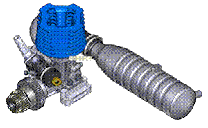
Take a model of an engine for example. Let’s assume the engine as a whole has 250 parts. Creating a work instruction from 250 parts is very complicated from a perspective of technically using the software and envisioning a proper procedure. The solution is to break the engine into configurations such as carburetor, gas tank, exhaust, etc. Now, that the model is broken up into these smaller, more manageable subsets.
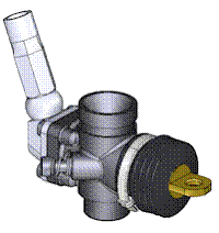
A configuration is a unique set of parts. Each configuration has it’s own exploded views and parts lists. Applied materials can differ between configurations. Merged models are managed independently between configurations too.
Suppression is the term used to describe the visibility of a part in a configuration. Suppressed parts in a configuration are not visible as long as the configuration is active. Suppressing a part is kind of like deleting the part, but only while the configuration is active.
You can select different configuration using the “Configuration” pulldown on the “Configuration” ribbon.
There are a variety of ways to create configurations. The most common is to create a new configuration from the visible or selected parts. You can also right click subassemblies in the tree to create a new configuration from the clicked subassembly. You can further tweak configurations by suppressing parts using the suppress tools. When the suppress tool is active, you can right click a suppressed part in the model tree and unsuppress it.
Disassemble – Create an Exploded View for Each Configuration
Since solid models are invariable worked with in an assembled state, the best way to create assembly procedures is to work backwards and start by creating an exploded view representing an ordered disassembly.
So in this step, you should select one the configurations that you created above and proceed to create a disassembly procedure paying close attention to the order of the steps.
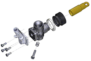
Once you create an exploded view, you will automatically enter the exploded view creation mode with the “Move” tool active. With this tool you can click on the first part that you want to move and then CTRL-click to add more parts to this movement. You can drag the axis that appears near the first clicked part to position the select parts. There are other ways to set this position too, such as bringing up the properties panel to type in exact movements. If the axis is not oriented correctly, you can try changing to one of 4 different axis options. These will align with the currently select part. You can select a different part or point to align to by clicking the “Change Axis” tool in the ribbon and then click on a part surface.
While creating exploded steps, you can hold down SHIFT temporarily to use the mouse to rotate, pan and zoon the 3D view.
As you create more and more steps, make sure to pay attention to the order of your steps. You can get a graphical view of this order and access to tools for managing this order by bringing up the “Exploded View Panel”. Using this panel, you can delete steps, reorder steps, and rename steps by right clicking on the step name.
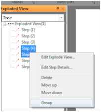
After you have created your steps, you may want to group some of these to create compound steps. These would be a set of steps that you would like to show in a single graphic. For example, you may have screws moving a certain distance and washers moving a little less. To create this you would have to create two steps because the distance or the direction of the movement is not the same for the screws and the washers. However, you might like for this to be showing in a sing instruction. The solution is to group these two steps together. To do this, click to select the first step that you want to group, then CTRL-click to add more steps. Once you have all the steps that you want to group selected, right click the selection and choose “Group”.
Create the Process – Automation with Smart Template Technology™
Once you have created an exploded view of the disassembly, you can use Smart Template Technology ™ to turn your exploded view into a series of illustrations representing your assembly process. Technically, you will use the “Storyboard Wizard”, select the desired exploded view and the program will automatically create a new storyboard with an illustration for each step that you created when you created the exploded view.
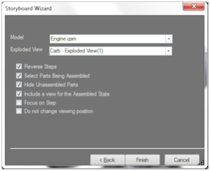
Using the Carb example from above we will create a assembly process. The first step is to activate the configuration (in this case “Carb”) and then adjust the working view so that you have the model in an orientation and render style that you will desire for many of your automatically created illustrations. You can adjust the illustrations individually later, but this is your chance to set up most of them correctly with the least amount of after creation effort needed.
Now, Go to the Illustrate Ribbon and from the Storyboard > Select pulldown choose “Storyboard Wizard”. This will allow us to designate a few parameters that will determine how the illustrations will be created. Make sure to select an exploded view. For assembly instructions, it is typical for users to check the first 4 options. Depending on your personal preference, you may not want option 2 which will automatically highlight the parts that are being assembled.

Automatically create storyboard – uses a disassembly exploded view to create an assembly process
Once you click “Finish” the program will automatically generate a set of illustrations. Each illustration will portray one of the steps from your exploded view and the viewpoint will be oriented as you set up in the working view before running the Storyboard Wizard. A lot of tedious work has been done by this process including hiding and showing of parts as they are relevant to the process, selection of parts being used in the current steps and the creation of a number of illustrations equal to the number of steps in your exploded view, but in reverse.
Detail the Illustrations – Modify individual Illustrations
Now that you have a set of illustrations to work with, you may desire to modify them by making the viewpoint more relevant, selecting additional parts, adding markups and callouts, changing render styles,etc.
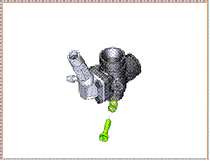
You can click each individual illustration to activate the illustration and review it. However, if you use your mouse to interact with the 3D view at this point, you are simply inspecting the model, you ARE NOT modifying the illustration.
To modify the illustration you will need to explicitly choose to “Edit Illustration.” You can do this from the Illustrate ribbon, or by right clicking on the illustration and selecting “Edit Illustration”. Once you are in Edit Illustration mode it will be clear because you will see an Orange outline around the illustration to indicate this.
At this point, any changes you make to the viewpoint, render style, and other properties of the view will be captured by the illustration. You can also add markups, etc from the Illustrate ribbon.
Once you are finished modify the illustration, you can click on the “Done” button in the top-right corner to capture the change. Notice that once you click the button, the thumbnail representing this illustration in the storyboard will update to match the changes that you made to the illustration.
Master Process– Create the Overall Procedure
This is a little different from the others because you will activate the “Master” configuration and will likely be working with all of the parts in your 3D model. However, you should create a disassembly procedure that works with large chunks of the parts so that each movement is moving one of the subsets or configurations that you created or any hardware that is used to put these larger chunks of parts together. There is no quick way to highlight just the parts in a specified configuration so you will have to select these parts manually when you are creating the master steps. While in Exploded View mode, you can use the model tree to select subassemblies.
Again, after creating a nice list of ordered steps, you may want to go back and group multiple steps together to form a compound scene with multiple part movements.
Once you are happy with the master procedure you will use the same steps as above to automatically create assembly process from your disassembly exploded view and then modify the resulting illustrations as desired.
Using Assembly Processes in a Document
You now have likely created a set of sub-processes, one for each configuration and possibly a single master process that brings all of the major components together. You can review and select any of the storyboards representing these process by switching to the Illustrate ribbon and using the Storyboard > Select pulldown. Individual illustration from a storyboard can be selected by clicking the thumbnail in the storyboard.
The next steps will involve using determining how you will use these various storyboards in the layout of your final document. This will depend on your desired delivery method… printed or interactive.
If you are creating a printed manual, then you will likely use Smart Template Technology in conjunction with a custom template page to automatically insert your illustrations into multiple pages of your document. Another method is to use the project panel and simply drag the desired illustration out to a document page and create a custom document on-the-fly.
If you are creating an interactive instruction document, you will likely use a template that has buttons for displaying the step-by-step process by animating between the illustrations in the storyboard.
Changelog
