Ballooned Exploded Views
Create an exploded view and add balloon markups.
Suggested Product: Publisher3D
Alternatively, this tutorial can be completed using Pages3D Professional after completion of the “Pages3D Primer” tutorial.
Creating ballooned exploded views is a common use of Publisher3D. There a a few steps to this and they will be covered in the next sections.
- Create an Exploded View
- Optionally, Create a Custom Parts List
- Assign a Parts List to the 3D View
- Save an Illustration to capture the viewpoint, set the exploded state and associate a parts list
- Add Balloons and other Markups
Exploded View Concepts
An exploded view has numerous uses in technical documentation. Uses range from a standard exploded view with balloons to an interactive step-by-step process.
- Exploded views include a list of part movements, called explode steps.
- A Publisher3D project can include multiple exploded views.
- Explode steps may include multiple parts
- Each explode step is one movement either move, rotate or scale
- Exploded steps can be organized into explode groups for simple organization or to create complex movements.
Once you have created an exploded view, you will generally create illustrations that reference specific explode states.
Create an Exploded View
Create an Exploded View
- Verify that the entire 3D model is visible. Right click the view and choose “Show All” if you are not sure.
- Select the Model Ribbon.
- From the Exploded Views pulldown, select “New Exploded View”.
- Name this one “Main Exploded View” and click OK.
- Observe that you are now in explode-edit mode. Notice the mouse cursor has change to indicate it is ready to select and move parts. Also, a “Done” button will be displayed in the top-right corner.
An exploded view is made up of 1 or more explode steps. Let's create the first step now.
Selecting the Parts for the First Explode Step
- Notice the two screws holding the “ST” plate in place. Left click one of these screws.
- Notice that the part is selected and an axis appears.
- CTRL-left click the other screw to select it too. By holding down control when you click, you add parts to the current step. By selecting both screws for this step, we will be able to move both of them at once.
When moving parts, the axis indicates the direction that the part will move. There are different axis options. The “By Object” axis will work well with this model since all of our movements will be aligned with the XYZ axis. Other axis are available that allow you adjust to different needs.
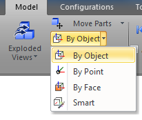
Exploded View Ribbon Group (Axis)
Upgrade Notice
The current release includes two new options "Expand Move Parts" and "Radial Move Parts".
Choosing the Exploded Step's Axis
- Click on the pulldown immediately below the “Move Parts” button to choose your move axis. Pick “By Object”. Once you have chosen an axis it will remain the active axis until you change it.
- Notice the “By Object” axis displayed in the 3D view. By dragging the axis handles, you can use this axis to move the part in any of these primary directions.
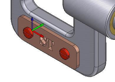
Explode Step Axis
Move the Parts with the Mouse
- Left click on the green axis, hold down the mouse and drag.
- Notice that the movement is restricted to the green axis. When the screws are positioned as desired, release the mouse button.
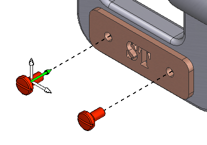
Congratulations, you have now created your first step in this exploded view. To create a final exploded view, you will repeat this basic process until all of the desired parts are moved into their final exploded position:
- Click on a part to create a new step.
- Add additional parts to this new step by holding down CTRL.
- Move the parts into position.
- Repeat.
We’ll cover some additional methods of selecting parts and moving parts in the next section.
Add Steps to the Exploded View
Create a Second Step
- Verify that you are in explode-view editing mode by making sure the “Move Parts” button in the Exploded Views ribbon group is highlighted and a “Done” button is displayed in the top-right area of your 3D view. If it is not, click the “Move Parts” button.
- Left click on the name plate part with the “ST” label. This will select the part and create a new step.
- Instead of moving that part by using the axis, we will type in a specific value. Right click the selected part and choose “Edit Step Details…” to bring up the Properties Panel.
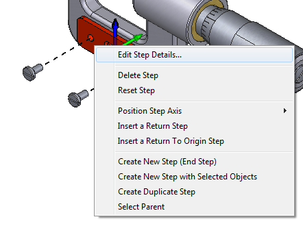
Move the Parts by Entering a Value
- Observe that the Properties Panel has a section titled “Type and Values” that provides an alternate method for setting the distance for the movement.
- In the Y field, enter a value of -0.02. If this results in too large of a movement or too small, adjust to your liking. Alternatively, you can use the slider to adjust the value.
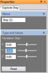
That’s it for that step. Now, on to the third step in this exploded view. In the third step, we are going to focus on moving an entire subassembly instead of a single part.
Display the Model Tree
- Click on the “Model Panel” button in the Model Ribbon. This will display the Model Panel which will enable a different method of selection while creating exploded view steps.
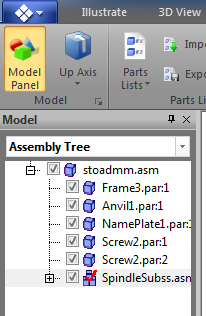
Moving a Subassembly
- In the Model Panel, click on the subassembly “SpindleSubss” to select that subassembly.
- Notice that this highlights all of the parts of that subassembly in the 3D view and displays the Axis, which should still be in “By Object” mode.
- Left click on the red handle of the axis and drag to adjust the position of the subassembly. Release the mouse button when positioned properly.
Another Subassembly Selection Method
Another way to select a subassembly instead of a part is available from the right click menu. Click on any part in the subassembly to select it, then right click that part and choose “Select Parent”.
With three steps finished, there is just one more movement that is needed to complete this simple exploded view. Let’s zoom in and pan to get a better view of the Anvil.
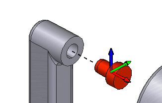
Moving the view and returning to edit steps
- In the Viewpoint ribbon group, click on Zoom.
- Click and drag the left mouse button to zoom in on the view.
- Now, click on “Pan”
- Click and drag the left mouse button to center the open area of the C-shaped frame in your 3D view.
- Now, click on “Move Parts” in the Exploded Views ribbon group top return to editing steps.
When we clicking on Zoom, we exited step editing mode. To re-enter that mode, we clicked Move Parts again.
Mouse Navigation while Editing Steps
You can also hold down SHIFT while in “Move Parts” mode to navigate the 3D view and never leave the mode. With SHIFT held down left click and drag to rotate, middle click and drag to pan and right click and drag to zoom.
For this step, we will use the Smart Axis instead of the “By Object” axis. The Smart axis is generally good at detecting the direction that is natural for a part to move and is especially helpful when working with uniformly shaped objects like screws, washers, plates, etc.
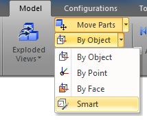
Create a Step using the Smart Axis
- Click on the Anvil to select it. You can click it with your mouse, or use the Model Tree.
- Notice that the axis is displayed as expected.
- From the axis pulldown menu, select “Smart”.
- Notice that the axis in the 3D view changed from a tridirectional axis to a unidirectional axis.
- Click on the red handle and use the mouse to drag the position of the Anvil. Release the mouse.
- Click “Done” in the upper-right hand corner of the view to exit exploded view editing.
- Notice that the axis is no longer display and the part selection reverts to the state of selection before editing.
- Click on “Home” in the viewpoint ribbon group.
We have now completed our first simple exploded view. Your 3D view should look like this:
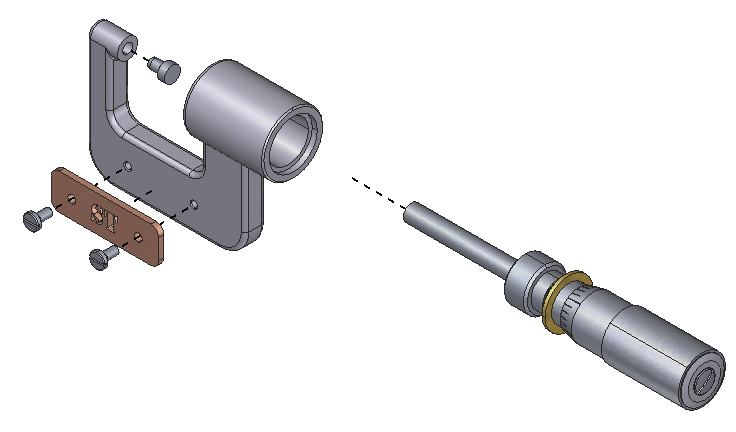
Explore the Exploded View
Now that we have created an exploded view, let’s explore some of the tools that will help you understand the organization and modify steps as needed. We will use the Exploded View Panel to view a hierarchical representation of our previous efforts.
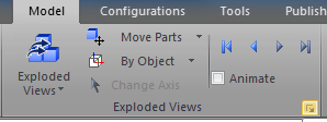
Exploded Views Ribbon Group
Exploring the Exploded View
- Click on the small button in the bottom-right are of the Exploded Views ribbon group. This will display the Exploded View Panel.
- Observe that the panel includes a tree of your exploded view. Each of the steps we created is listed under the name of the exploded view.
- Click on the top of the tree, “Main Exploded View”. This will collapse the view entirely.
- Now, click on “Step(1)”.
- Notice that the 3D view displays only the movement of the screws.
- Click through each of the other steps listed and observe how the 3D view behaves.
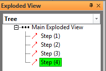
Exploded View Panel
The tree can also be used to edit and existing step, reorder the steps, or delete steps that are no longer needed.
Exploded View + Illustration Concepts
It is important to note that an exploded view is not an illustration. In the following sections, we will use the exploded view as the focus of a new illustration.
An exploded view is simply a series of exploded steps as we just created.
The illustration will save the exploded view state along with the viewpoint, the render style, an optional markup layer, and other view attributes. You can have multiple illustrations “looking at” the same exploded view.
Parts List Concepts
When a 3D model is imported into Publisher3D, a master parts list is automatically generate. The parts lists will include a row for each unique part. Often the master parts list is suitable, but there are many cases where it must be customized or a new parts list created.
Publisher3D include extensive tools for creating, editing, managing, importing and exporting parts lists.
Publisher3D supports multiple parts lists. This is useful for technical documentation, as often different 3D views with balloons are based on a subset of parts. By creating a parts list for the specific view, we can easily guarantee that the balloons in the image match the call numbers in the parts list.
View the Current Parts List
The 3D view is always associated with a parts list.
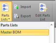
View a Parts list in the Model Panel
- Select the Model Ribbon
- Click on the “Parts Lists” button in the Parts Lists ribbon group.
- Observe that this will list all of the parts lists in your current configuration (more on configurations later). For now, just think of this as all of the parts lists in your project.
- Notice the “Master BOM” is currently selected indicating that this current 3D view is associated with this parts list.
- Click on “Master BOM”.
- Observe that the Model Panel is displayed. Notice that this is the same panel that we have used previously to gain access to the assembly tree. However, it is currently displaying the “Master Parts List” instead of the assembly tree.
- Use the pulldown at the top of the model panel to select “Assembly Tree”.
- Notice that the panel now displays the familiar assembly tree.
- Now, use the pulldown to return to the “Master Parts List”

When the model panel displays a parts list, you see a list of rows with quantity displayed in parenthesis. You can click on rows to select and use the checkboxes to hide and show the parts in a row.
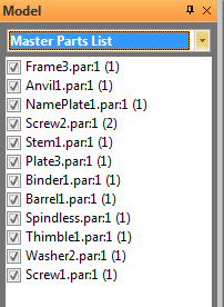
Another way to view the current parts list is to view it in the feature-rich parts list editor.

Activating the Parts List Editor
- From the Parts List ribbon group, click on “Edit Parts” list.
- Observe that the software switch to edit parts list mode and displays a tabular view of the current parts list. Also, notice the done button in the top-right indicating this mode.
- Click “Done” after viewing the parts list. We will learn about editing in a later session.
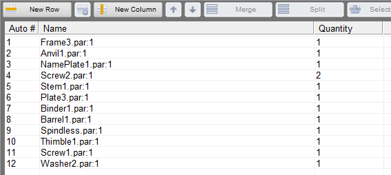
About the Master Parts List
The Master Parts list is a generated list that includes all parts in the model or configuration. These master parts lists are automatically updated when parts are added or suppressed in a configuration. This automated update of the master parts lists means the manual changes that you make to the master parts list may be lost if the configuration is changed. We will learn more about configurations and suppression later in the training.
It is best to create a custom parts list if you intend to customize the rows or otherwise make changes to the parts list.
Illustrations + Parts Lists Concepts
When you create a new illustration, the current parts list is saved with the illustration too.
Since the illustration is associated with a parts lists, markups can display text from the parts list. A primary example of this is using the parts list to define the balloon numbers automatically. The parts list can also be used to display metadata fields of a part too.
Create a Custom Parts List
In our current exploded view, we are only focused on a subset of the parts in the model. If we used the master parts list to define the balloon numbers, we would not get the desired result. There few ways to create a custom parts list:
- Create from “top-level” only to create a parts list where subassemblies were listed as a single line item (we will use this technique here)
- Create from the current selection set
- Create from the current visible set of parts
Once we have created the parts list, then we can edit it and customize it as desired.
- Select the Model Ribbon
- Click on the Parts List pulldown and then choose “New Parts List”
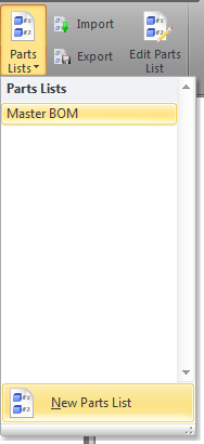
Setting up a new Parts List
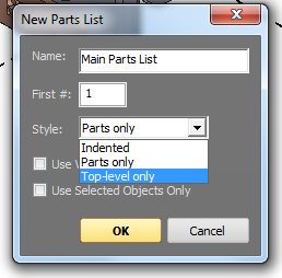
£ Observe that this displays a dialog that is used to let the software know which parts should be listed as line items.
£ Name the parts list “Main Parts List”
£ Select “Top-Level Only” from the Style pulldown
£ Leave the options for Visible and Seletected Object unchecked.
£ Click OK
Explore a New Parts List
- Notice that the software changes to part list editing mode and the tabular view of the parts list is displayed along with the now familiar “Done” button.
- Notice that the process created a new parts lists with just the 5 items that we want on the list for now.
- Click “Done” to exit part list editing mode.

Create A Fourth Illustration
Now that we have a parts list that matches our recently created exploded view, we are ready to create an illustration that ties it all together.
Edit an Illustration
- Click on the Illustrate Ribbon.
- Click “Home” from the viewpoint panel to position the 3D model
- Click “New” in the Illustrate ribbon group
- When the new illustration dialog is displayed, change the name to “Ballooned View”. Keep “Edit Markups Now” checked
- In the Illustration Tools ribbon group, click on “Callout”

Add a Balloon Callout
- Observe that we are now in edit markups mode. You will see the grid and the “Done” button.
- Click on a screw to set the position of end of the leader, hold down the mouse and drag to position the balloon.
- Observe that a number is automatically assigned to the balloon. The balloon numbering is determined by which part was clicked when the leader was set and the call number that was assigned to the row that includes the clicked part.
- Right click the number and select “Properties”. This will display the Properties Panel for the newly created callout.
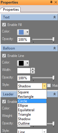
Edit the Callout Properties
- From the Properties Panel, set the balloon style to “Circle” and set the color for the balloon and text to black.
- From the Font ribbon group, set the font size to 14.
- Also turn off bold and italics from the Font ribbon group is they are currently highlighted.
- Again, click on “Callout” then click on any part in the subassembly and drag out to place the balloon.
- Observe that the properties of the second balloon and consistent with the first and the visual adjustments do not need to be made a second time. Also, notice that the call number for the subassembly is ‘5’ which matches the custom parts list that was created previously.
- Create callouts for the remaining three parts .
- Click “Done”.
Your view should look like this:
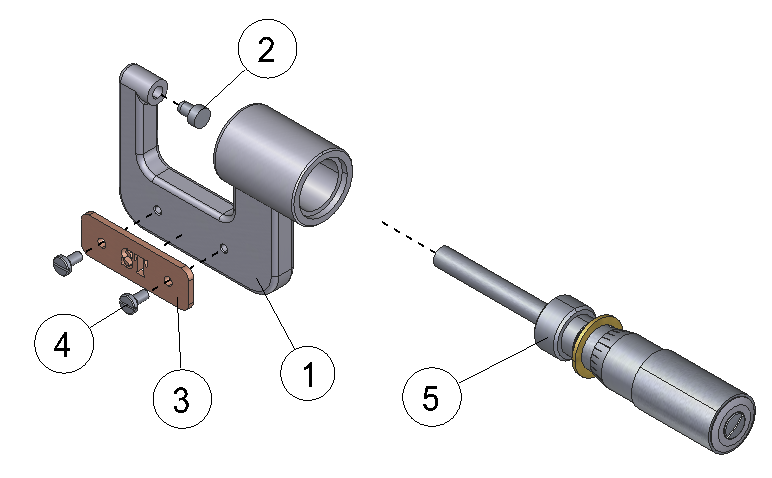
Setting Markup Tools to Stay Active
You can set your markup tools to stay active as you add markups. This is useful for people that do a lot of balloons. This option can be found from the Application Menu > Preferences, check “Keep Last Selected Markup Tool Active”.
Updated less than a minute ago
