Document Authoring with Pages3D
Learn how to add images, text and tables to your Pages3D document.
Required Product: Pages3D
Pages3D Workflow Overview
You create documents using Pages3D and the following basic workflow:
- Import 3D Models
- Create pages of information
- Create graphics and animations from 3D
- Publish the document for printed or interactive delivery.
Getting Setup for this Section
If you have just completed “A Pages3D Primer”, then you will have Pages3D open and 3D model imported. If you are returning to Pages3D, you will need to open up your saved off QSD from “A Pages3D Primer”.
Open a Saved QuadriSpace Document (QSD)
- Click on File > Open
- Navigate to the directory where you saved the Pages3D Primer results and then select the QuadriSpace Document (QSD) saved there, probably names: “pages3d_primer.qsd”
- Make sure you are in Page Layout editing mode. On the Home ribbon, observe the state of the “Edit Page” button.
- 'If the “Edit Page” button is not highlighted, click it to enter Page Layout editing mode.
Your page should now look like this:
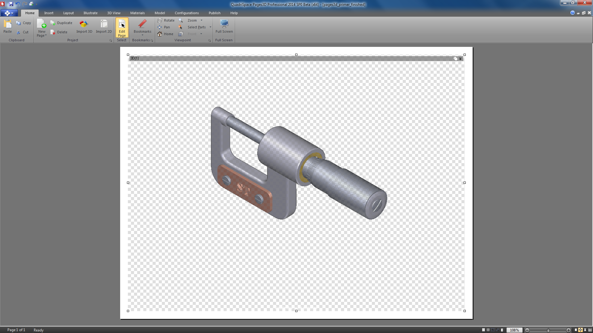
Now, save it with a new file name. This will allow us to maintain the basic QSD file we created in the first Pages3D section and will provide a more descriptive filename for the current session. For this training, it is good practice to save a unique file for each section that you complete.
Save with a New Filename
- From Application menu, choose “Save As…”.
- Enter “pages3d_document_authoring.qsd” as the filename.
- Click “Save”.
The Goal of this Section
Now, we are setup and ready to proceed. In this section, we will create a single-page document with the following features:
- Interactive 3D view
- Title and other formatted text
- Bidirectional, interactive parts list with custom formatting
- Dynamic display of part metadata
- Logo Image
- 3D PDF-Ready
Page Element Concepts
A Pages3D document is a series of pages each containing any number of page elements. Page elements can be anything from a simple text box or image to an interactive 3D view or clickable parts list. Each of these page elements can be created and then positioned on the document page. As you explored in the Pages3D Primer section, when you toggle the “Edit Page” button to turn Page Layout editing mode on an off, you change the way that the page element is affected by mouse interaction.
Generally, page elements are created using the tools available from the “Insert” ribbon. Some example page elements include:
- 3D View
- Text Box
- Image
- Table
- Parts Table, which dynamically displays part metadata
- Illustration Text, which dynamically displays illustration metadata
- Shapes, connectors and other page design elements

Review the Insert Ribbon
- Click on the Insert Ribbon
- Observe the various page elements organized into four groups: text, tables, graphics and views.
- Notice that the Insert ribbon also includes the “Edit Page” button for easy access.
Add an Image Element to the Page
Let’s add a simple image to our document.
Cue an Image Element
- Click the “Insert” ribbon.
- Click on the top part of the Image button, or use the pulldown menu below the image button to pick “Select Custom Image”.
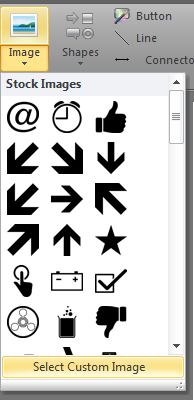
Drag out an Image Element
- Observe that placing your mouse over the document page displays a mouse cursor indicating that it is ready to drag out a new page element.
- In the top-right are of the page, left-click and then drag out a rectangle, then release the mouse.
- When the mouse button is released, a dialog will display asking for the image to import.
- Use the file dialog to browse to the “Elements” directory in your training folder. Click on “abc_company.png” and then click “Open”.
- Notice that the rectangle is now replaced with the image of the ABC Company logo.
- If your image has a border around it, you can turn this off by clicking on the “Line” pulldown in the Colors ribbon group and then choosing “No Line”.
Your document page should now look like this. It should include a 3D view and a logo image.
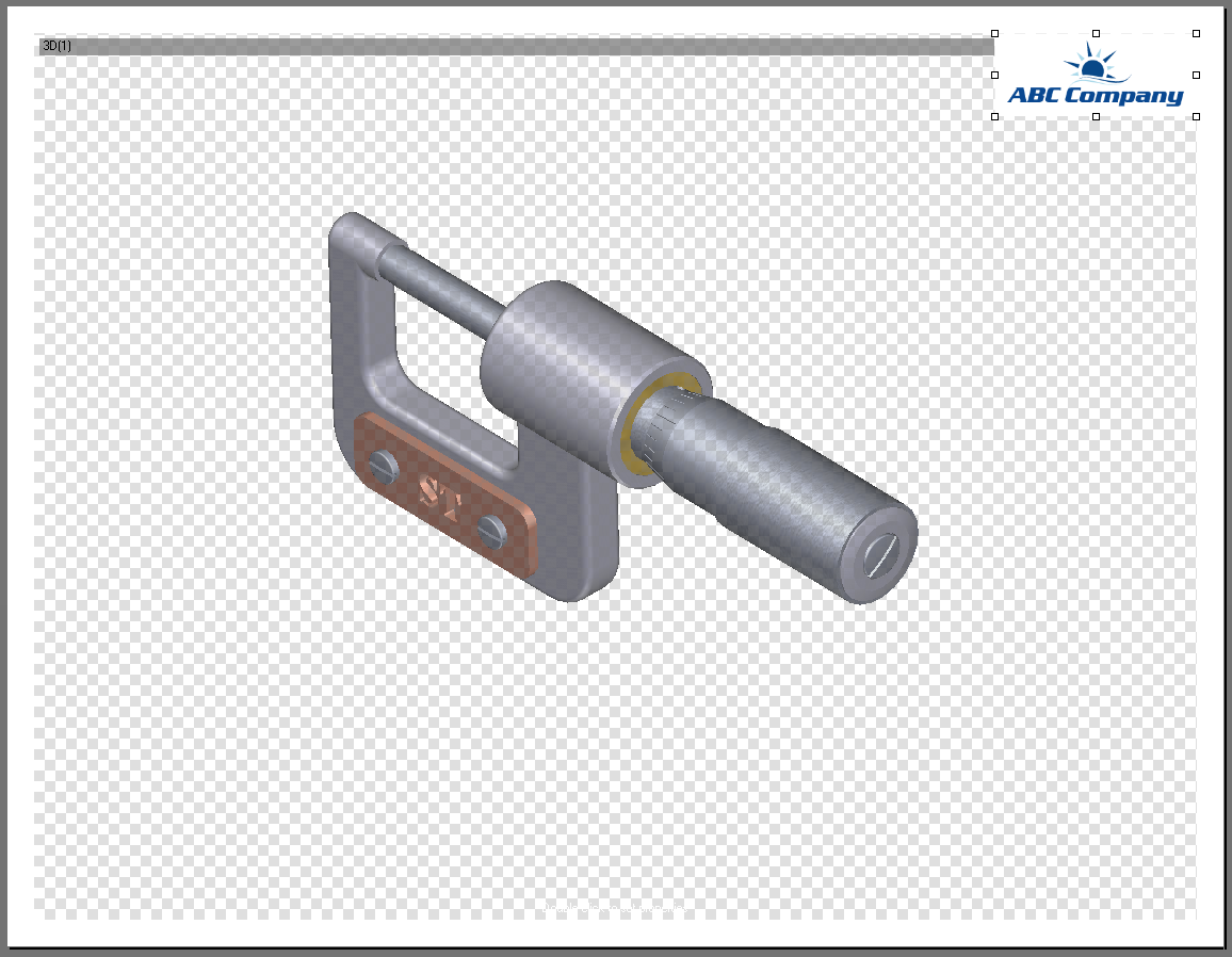
Positioning Page Elements
Previously, we learned how to position and resize a page element when “Edit Page” is active. To summarize, we learned:
- Clicking the middle of the page element and dragging it will move the element
- Clicking on the handles on the corner of a selected page element will resize it
- Right-clicking a page element and choosing from the “Position” submenu will allow you to use some preset positions, like full page, to rapidly set the position of the page element.
- For more precise positioning, you may need to use the grid or the margins.

Setup and Enable the Positioning Grid
- In the bottom-right of the user interface click on the “Toggle Grid” button.
- Observe that around the edges of the 3D view, some grid lines are displayed.
- Click on the 3D view page element to select it. This will display the handles around the view.
- Click on the bottom-right handle, hold down the mouse and resize the view.
- Notice that as you resize the view with the grid on the position will snap to the grid.
- Resize the 3D view so that it fills an area of 7” x 5” starting 1” from the top and 1” from the left. If you are using metric units, you can resize the view so that it fills an area of 17.5cm x 12.5cm starting 2.5cm from the top and 2.5cm from the left.
- Now select the logo image, then move it until the top-right corner snaps to the top-right corner of the document page.
- Now, using the bottom-left handle, resize the logo image so that the height of the image is it 0.75” (or 2cm). The width will be determined by the aspect ratio of the image.
The grid is versatile and can be set up with your preferred units, or subdivisions. Your installation may either default to inches or centimeters.
Your document page should now look like this:
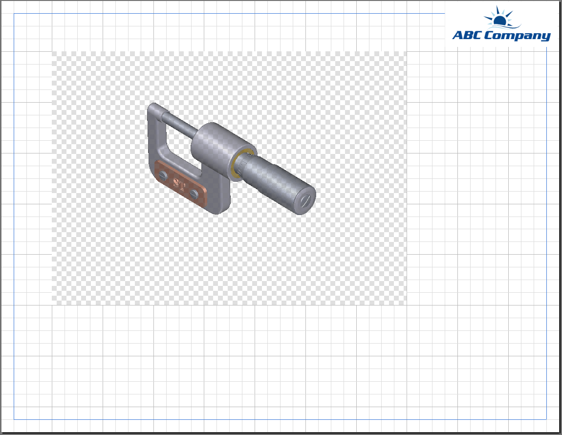
Adjusting the Grid Spacing
The grid subdivisions can be adjusted using the two buttons next to the “Toggle Grid” button. The first button will decrease the subdivisions and the second button will increase the subdivisions.
Add a Title
Pages3D makes it easy to add text and position it on the document page.
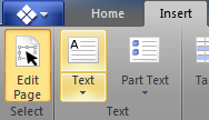
Add a Text Box
- Click on the “Insert” ribbon.
- Click on the “Text” button.
- Observe that when the mouse is positioned over the document page that the cursor changes to indicate that it is ready to create a new page element.
- Hold down the left mouse button. Starting at the grid location 1” from the left and 0.25” from the top, drag out a text box and release 0.5” below the starting point and near the logo graphic.
Like this:

Set the Font Size
- Now, in the text box, type “ST Micrometer Parts Lists”.
- Observe that the resulting font size is determined by the size chosen in the the Font ribbon group.
- Use the mouse to select all of the text in the text box.
- From the Font ribbon group, select “24” for the font size.

View the Text in Interactive Mode
- Notice that since you are still in Page Layout mode, the grid and selection indicator are still displayed.
- To view the page like it would be when finished, click on “Edit Page” to toggle off Page Layout mode.
- Observe that the 3D view no longer has a hatch overlay and that the grid disappears. These are indications that you are not longer in Page Layout mode.
- Click on “Edit Page” again to turn it back on for further editing.
Dynamic Table Concepts
A unique capability of the Pages3D software is the ability to insert dynamic tables onto a document page. These tables are efficient for authors because they are automatically populated. The most commonly used dynamic table is the Parts Table. These are automatically generated parts list tables added to a document page which display part metadata as cell contents. The table’s column fields and the part data are both customizable as needed.
These tables can be used for printed manuals or as clickable interactive page elements. For example, when the Parts Table is set up with interactive features, clicking on the table will select the parts in the 3D view and clicking in the 3D view will select the corresponding row in the table. This is referred to as a bidirectional association between the table and the 3D view.
There are two other types of automatically generated tables. The Illustration Table is automatically populated with illustration metadata, such as the illustration name or description. The Step Table, is used less frequently, but is populated with exploded ste3pe metadata.
Insert a Parts Table
Before we add the table, let’s make room for it on our document page.
Resize the 3D View
- Click on the Insert ribbon.
- Make sure “Edit Page” is on.
- Click on the 3D view.
- Drag the right handle to decrease the width
Like this:
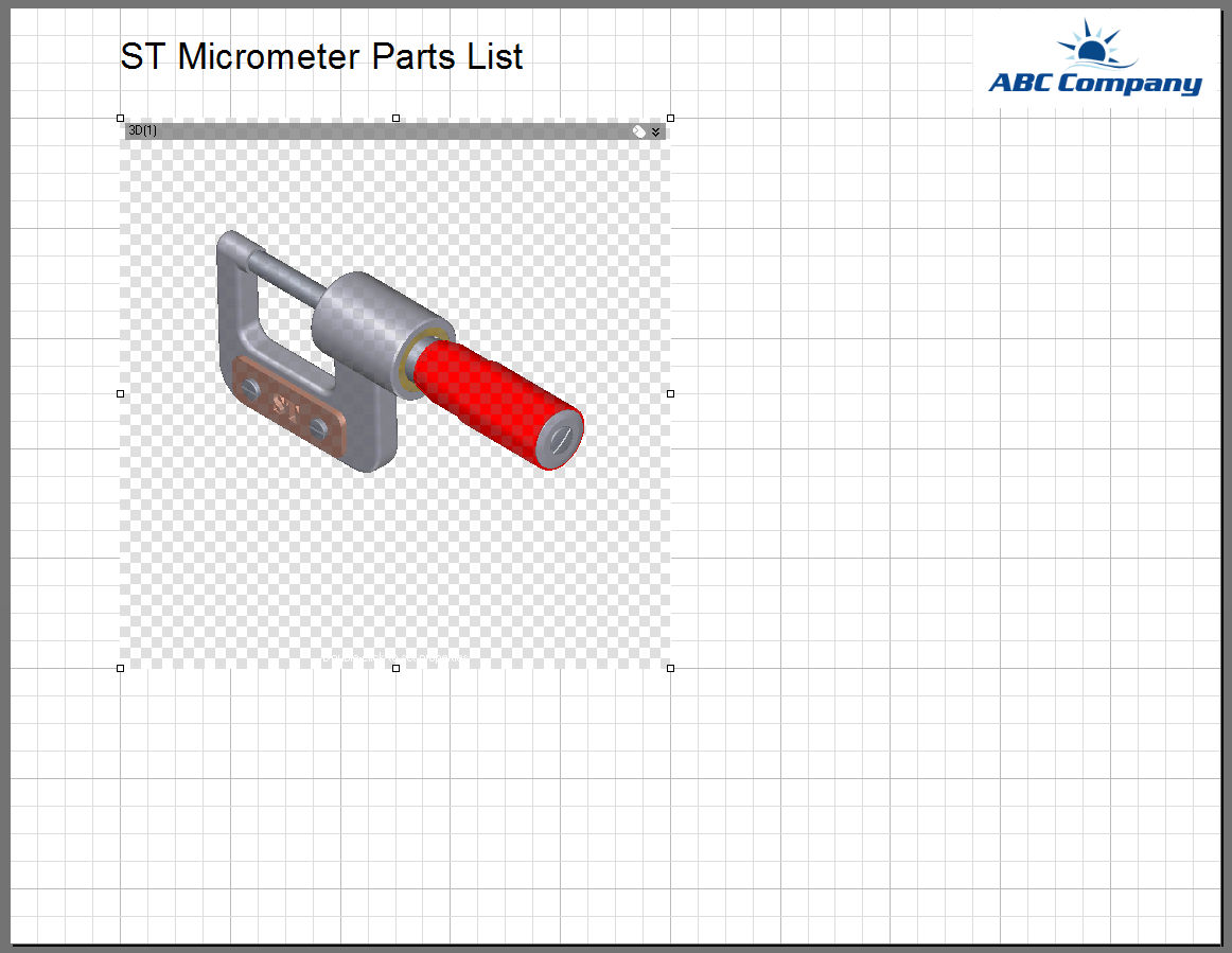
Now, we are ready to add the dynamic parts table.

Insert a Dynamic Parts Table
- Click on “Parts Table” in the Table ribbon group to activate the parts table tool.
- Click on the page and then drag out a box to the right of the 3D view starting about 0.5” to the right of the 3D view and extending to about 1” from the right page border.
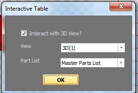
- Observe that when you release the mouse button, a dialog will display prompting you to choose whether the table is interactive and if so, the settings.
- Click on OK to accept the default settings, which will set the table up with interactivity.
Initially, table formatting is determined by the current settings in the Font, Paragraph and Colors ribbon groups. Since we last changed the font to set the title size to a large font our initial table font is very large. Visually, the table is also very customizable with row colors, headers, and more.
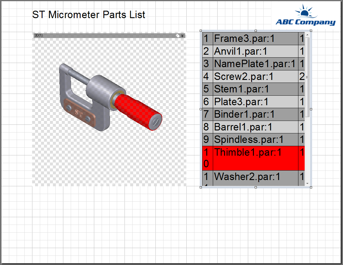
Let’s start with changing the font to better match the needs of this table.
Format a Dynamic Parts Table
- Click on the parts table to select it.
- From the Font ribbon group, choose a font size of “12”.
- Observe the change to the parts table.
Now, let’s explore some of the properties that will allow us to make this table look nice.
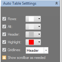
Right click the table and choose “Properties…” from the popup menu.
Notice that this displays the Properties Panel with the tabs for setting the tables properties.
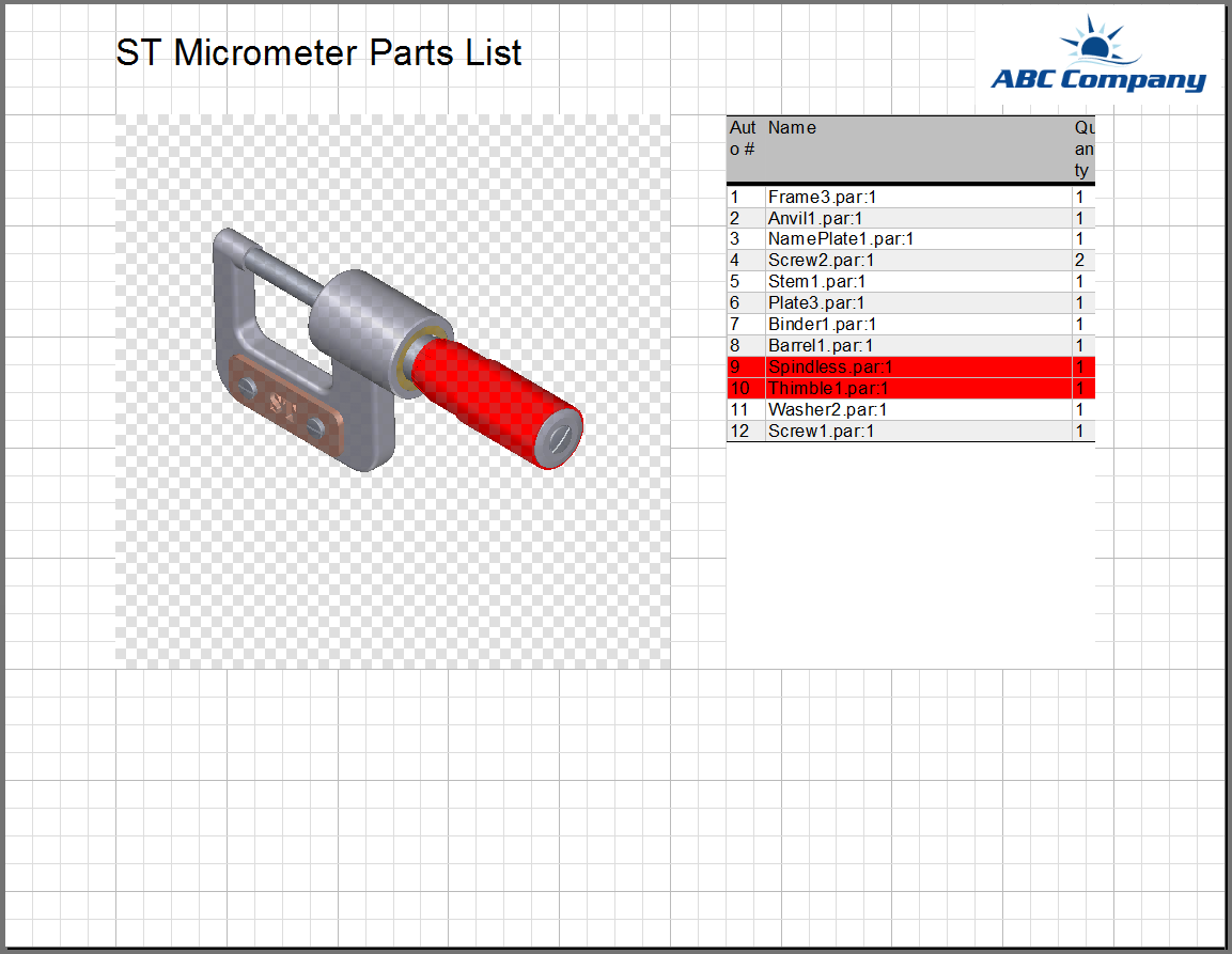
Congratulations, you have now added a bidirectional parts list to a document page!
Updated less than a minute ago
