Your First 3D Illustration
Learn about Storyboards, Illustrations, Render Styles, Sections and more.
Suggested Product: Publisher3D
Alternatively, this tutorial can be completed using Pages3D Professional after completion of the “Pages3D Primer” tutorial.
Storyboard & Illustration Concepts
An Illustration is a named 3D view that can be created, edited, and recalled during the use of the Publisher3D software. Also, many publish options will offer methods for recalling illustrations.
- Viewpoint – the viewing position of the 3D scene
- Render Style – the style that is used to render the 3D scene
- Explode State – the exploded view and the exploded step
- Section – The state of the section planes
- Parts List – An associated parts list
- Metadata, such as the commonly used “name” and “description”
The Storyboard is a named collection of illustrations that provides an intuitive method of organizing illustrations. Each Publisher3D project can include multiple storyboards, if needed. A storyboard determines the following:
- Any number of illustrations
- The order in which the illustrations will be displayed
- Optionally, a transition and timing between the illustrations for animations
Let’s display the Storyboard Panel so that as we create illustrations in the next sections, we will see how the storyboard panel is populated.

Storyboard Ribbon Group
Show the Storyboard
- Select the Illustrate Ribbon
- From the Storyboard Group, click on “Show”
- Observe that the Storyboard Panel is displayed along the bottom of the user interface. You will notice that it does not contain any illustrations.
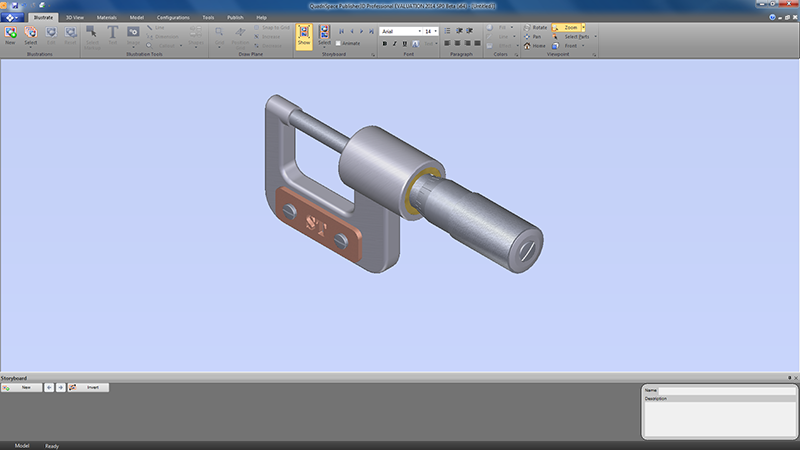
Storyboard Panel without Illustrations
Create Your First Illustration
When using Publisher3D, the goal is to create a set of illustrations for graphical content. These illustrations will be organized using the Storyboard and finally published. Let’s create our first illustration.
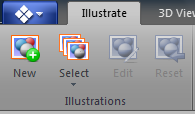
Illustrations Ribbon Group
Create an Illustration
- Select the Illustrate Ribbon
- From the Illustrations ribbon group, click on “New” (or click on “New” from the Storyboard panel)
- This will display a dialog box allowing you to name this illustration. Name this one, “My First Illustration”.
- Uncheck “Edit Markups Now”
- Click OK to create the new illustration.
Observe your First Illustration
As you create new illustrations, they will be saved with your Publisher3D project and you can recall them at any time. Since the Storyboard Panel is displayed, you will notice that your newly created illustration is presented as a thumbnail. If the thumbnail is not yet available, then you will see an exclamation point icon indicating that the thumbnail will be rendered soon.
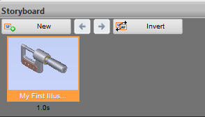
Storyboard with one illustration
Recall an Illustration
- Use the mouse to move the 3D viewpoint into an arbitrary position.
- Click on the thumbnail of the illustration to recall it. Notice that the main 3D view immediately displays the clicked illustration.
Set Precise Viewpoints
Often when creating technical graphics it is important to use industry standard viewpoints. For example, the Home button automatically centers the view and sets it to an isometric viewpoint. Using the viewpoint panel enables unlimited viewpoint selection.

Viewpoint Ribbon Group (Rotate)
Display the Viewpoint Panel
- Click on the small button Extended Group Property located in the bottom right corner of the Viewpoint group to display the Viewpoint Panel.
The small Extended Group Property buttons are located throughout the program and when clicked bring up an advanced panel relevant to the ribbon group that they are associated with.

Extended Group Property Button
The viewpoint panel provides an easy way to “dial-in” precise viewpoints.
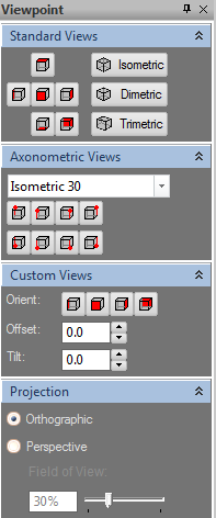
Viewpoint Panel
Explore Standard Viewpoints
- Observe the effect on the 3D view when you click on the buttons in the “Standard Views” panel group. (These views are also conveniently available as a pulldown on the Viewpoint Group on most Ribbons.)
- From the “Axonometric Views” group, click through the 8 buttons. Notice that each button represents a position, such as top-front-right or bottom-front-left and that as these are clicked the “Isometric 30” Axonometric view is applied.
- Now, from the pulldown in the “Axonometric Views” group, select “Trimetric 15-50-35”. Notice that the last position is maintained but the new axonometric view is applied.
- Click through the 8 buttons and observe.
The “Custom Views” group lets you dial in an exact viewpoint. To use this you will select an initial starting position from front, left, right or back and then modify the offset and tilt of the camera to get a desired viewpoint.
Explore Custom Viewpoints
- From the “Custom Views” group, click on the Front button. If you are unsure what the icons indicate you can mouse over to get a tip. Your model will orient to the Front view.
- For the Offset, type in “30.0”
- For the Tilt, type in “45.0”
- Observe that the model is now oriented 30 degrees to the left of the front position and 45 degrees above
- Now, change the Tilt to “-45.0” (note the negative sign). This will set the viewing position below the model.
Select and Hide Parts and Assemblies with the Mouse
It is often necessary to select parts. Sometimes part selection is simply used to highlight a specific part visually. Other times, features included with the software require part selection.
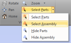
Viewpoint Ribbon Group (Select Parts)
The Viewpoint group included on most ribbons includes a number of mouse modes for part or assembly select and hide functions.
Selecting Parts with the Mouse
- Click on “Select Parts” in the Viewpoint group
- Hold your mouse over the 3D view and observe the cursor that indicates part selection. The solid cursor arrow indicates selection.
- Left click on a part.
- Observe that the part changes color to indicate that it has been selected.
- Click on another part.
- Observe that the first part your selected was deselected and the recently selected part is now the only selected part.
- Now, click on one of the screws near the ST logo. This will select it.
- Hold down CTRL and then click on the other screw. Notice that when you held down CTRL, the clicked part is added to the selection set and the already selected parts remain selected.
- Left click on the background of the 3D view. Make sure that you do not click on any part of the model. This will clear the selection set.
- Observe that the screws were deselected and the selection set is now empty.
Another useful selection mouse mode is “Select Assembly”. In this example there is only one subassembly which is the spindle.
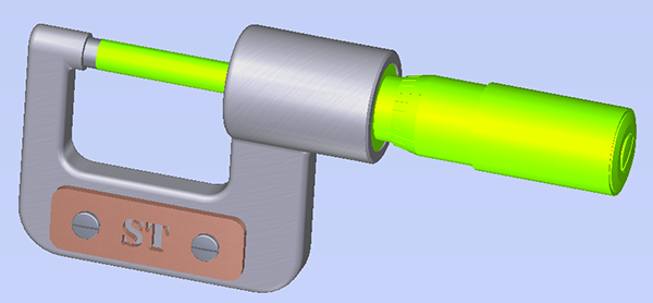
Subassembly Selection
Selecting Assemblies with the Mouse
- Click on the pulldown arrow next to “Select Parts” and choose “Select Assembly”.
- Observe the mouse cursor for selection now includes a small assembly indicator.
- Left click the part of the model that extends away from the C-Frame.
- Observe that the entire spindle assembly is selected.
- Now, click on the background in the 3D view where there are no parts to deselect all.
You can also hide parts and assemblies in the same way.
Hiding Parts
- Click on the pulldown next to “Select Assemblies” and choose “Hide Parts”.
- Observe the mouse cursor for hiding parts. The white cursor arrow indicates hide.
- Left click on various parts to hide them.
- Now, right click the 3D view and choose “Show All” from the popup menu.
- Observe that the parts that were hidden are now visible again.
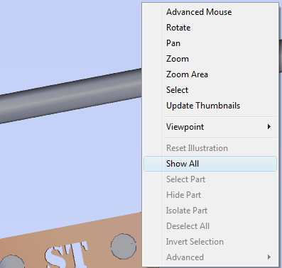
Right-click Menu (Show All)
CTRL and SHIFT
Holding down CTRL and left clicking a part will add the clicked part to the selection set. Holding down SHIFT and left clicking a part will hide it.
Using the Model Tree to Select and Hide Parts
Many 3D CAD models are organized into subassemblies and individual parts. To work with this assembly tree you will use the Model Panel.
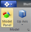
Model Ribbon Group
Displaying the Model Panel
- Select the Model Ribbon
- From the Model ribbon group, click on “Model Panel” to display the Model Panel.
- When the panel is first displayed, you may need to click the plus sign next to the CAD model name to open up the assembly tree and view the parts and subassembly.
- Click on on the plus sign next to the “SpindleSubss” to display the parts in that subassembly.
The Model Panel presents a hierarchical view of the imported 3D model. This should match the organization from the 3D CAD tool that created the model.
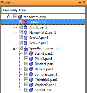
Model Panel
Selecting Parts with the Model Panel
- In the Assembly Tree, left click on the item labeled “Frame3”.
- Observe that this selects that part in the 3D view and places a check next to the part in the assembly tree indicating selection.
- Now, hold down SHIFT and click on the part labeled “Name Plate”.
- Notice that this allows multiple selections and now the top three parts here are selected.
- Next, hold down CTRL and click the part labeled “Spindless” inside the subassembly.
- Note that this adds the newly selected part to the selection set.
- Click on the top element of the tree to deselect all.
The assembly tree can also be used to hide parts and subassemblies.
Hiding Parts with the Model Panel
- Click on the checkbox next the “SpindleSubss” item.
- Notice that when the check box is not checked, then the subassembly is not visible in the 3D view.
- Click the checkbox again to enable the check and unhide the subassembly.
You can also select parts and subassemblies and then right click the tree to gain access to other options through a right click menu. Isolate is a powerful option here that will hide all of the parts and isolate the selected parts. There are other advanced option to that help maintain large sets of illustrations over time.
Adjust the Render Style
Render Styles are used to select and even customize the way the 3D scene is rendered. When a render style is selected, it is applied to the entire view. Since illustrations record the render style, each illustration can have it’s own render style applied to it.
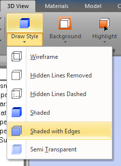
Render Style Ribbon Group (Draw Style Selection)
Using Preset Render Styles
- Select the 3D View Ribbon
- From the Render Style pulldown, select “Shaded with Edges”
- Observe that the view of the 3D now displays edges.
You can also modify specific render styles attributes. The most common options are easily available form the Render Style ribbon group.
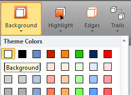
Render Style Ribbon Group (Background Color Selection)
Customizing the Render Style
- Click on the “Background” pulldown and select a white background color.
- Now, select an object in the 3D view. You can use any of the tools you learned previously, or CTRL-left click the C-shaped frame part. (If you have other parts selected, you can right click the 3D view and choose “Deselect All”)
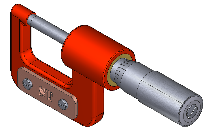
- Then, click on the “Highlight” pulldown and select the top shade of red.
- The Highlight color applies to the selected objects in the 3D view. Make a note that if you do not have a current selection, then the change will occur, but will not be immediately visible.
Your 3D view should now look like this:
Create a Sectioned View
The sectioning tools allow you to create versatile sectioned views of your 3D model.
Sectioned View Setup
- Select the 3D View Ribbon
- Click on the “Edit Section” to enable the sectioning mode
- Notice that when the “Edit Section” is pressed, the 3D view will display the section plane for editing, and the Properties Panel is displayed with the relevant properties. Also, you will notice a large “Done” button in the top-right area of the 3D view. This button indicates that you are in an alternate mode of the program.
- Click on “Enable Section View”.
- This will activate the section plane and display a visual guide in the 3D view. Notice that the 3D model is not sectioned at this point. We need to adjust the section planes.
- It is generally easiest to work with sectioning from a standard view such as Front, Right, Bottom, etc. This allows you to easily see the section planes.
- From the Viewpoint Group, select “Front”.
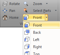
Viewpoint Ribbon Group (Selecting Front)
Section View - Adjusting the Plane
- Now, from the Properties Panel, click on “XY” to pick the section plane orientation.
- At this point, you should see a solid red line and a solid blue line indicating the section planes. You may nee to zoom out just a little to see these lines.
- We are not ready to adjust the plane. Use the red slide to adjust the plane so that it is positioned through the top half of the C-shaped Frame. Like this:
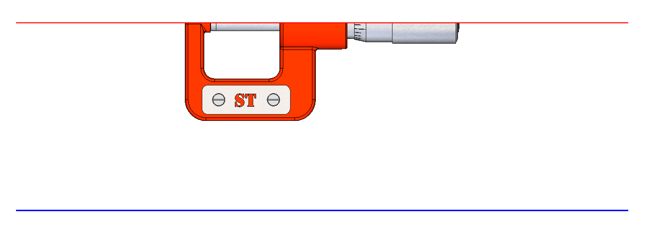
Adjusting the Section Plane
Section View - Viewing the Results
- Now, use the Viewpoint group to select the rotate tool and rotate the model so that you can see the sectioned model in 3D. Since the sectioning tools are still active, the planes will also be visible.
- Click on the “Done” button in the top-right to exit section editing. This will hide the properties and the section plane indicators. The section plane will still display the sectioned model.
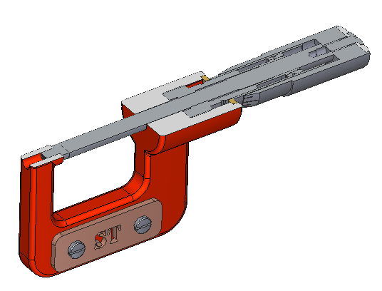
Viewing the Section Plane
It is also easy to create a view that sections only specific parts. In our example, it would be nice to section only the C-shaped frame. The section plane can be set to section only the selected parts or only the unselected parts. In this example
Apply the Section to only the Selected Parts
- Make sure that the C-shaped frame is selected. If not, hold down CTRL and click on the frame.
- Click on the “Edit Section Plane” button to enter section-editing mode once again.
- Observe that the sectioning tools and properties are again displayed.
- Now, in the Properties Panel, check “Selected Objects"
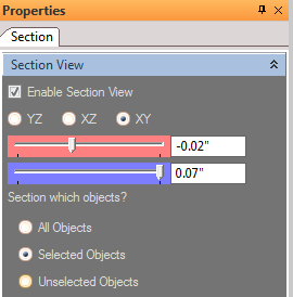
Section Selected Objects Only
Observing a Partial Section
- Observe that the 3D view is updated and now only the selected parts are sectioned.
- Click on “Done” to exit section-editing mode.
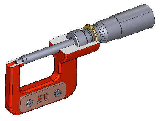
Viewing a Partial Section
Updated less than a minute ago
