Your Second and Third Illustrations
Continue creating illustrations and learn about markups.
Suggested Product: Publisher3D
Alternatively, this tutorial can be completed using Pages3D Professional after completion of the “Pages3D Primer” tutorial.
Create a Second Illustration
That’s a nice graphic. Let’s save it as an illustration.
Create Another Illustration
- Click on the “New” button in the Storyboard Panel.
- Name this illustration “Sectioned View” and like before uncheck the box next to “Edit Markups Now” (If you accidentally click OK without unchecking this box, just click the Done button that appears in the top-right of the view before proceeding.)
- Observe that your Storyboard Panel now displays your first illustration and the sectioned one that you just created.
- Explore clicking back and forth between each thumbnail in the Storyboard Panel. Notice that the 3D view changes to reflect the viewpoint, render style and section properties saved with each illustration.
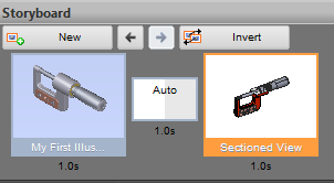
Storyboard with a transition between two illustrations
Use Transitions to Animate
When the second illustration was displayed in the Storyboard panel, an extra block was added between the two illustrations. This block, labeled” Auto” by default”, represents the transition and timing during an animation.
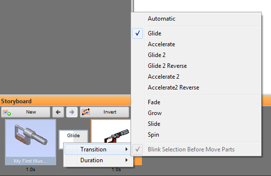
Right-clicking to edit a transition
Edit the Transition
- Click on the box labeled “Auto” between the illustrations.
- Observe that the view immediately displays the illustration preceeding the transition and animates through to the illustration that follows the transition.
- Right-click on the transition to bring up a menu for setting the transitions properties. You can set the type of transition and the timing from this menu.
- From the menu, choose Transition > Accelerate
- Right click again, and from the menu choose Duration > 5.0s
- Now, click the transition again, notice that it is now labeled “Accel”.
- Observe that the 3D view animates slower this time, taking 5 seconds to complete
There are other transition options available. The transitions that include a 2 are used when there are moving parts and a moving viewpoint. The 2 indicates that half of the time the transition will be moving the part and the other half of the time the viewpoint. Since we do not yet have any moving parts, we can ignore these options until later.
Reset the 3D View
There are times when you would like to disable the current illustration and start from a clean 3D view. For example, the second illustration currently has a section view setup. At this point we are ready to create a new 3D illustration that does not have the section plan active.
Reset the View
- Click on the “Section View” illustration in the Storyboard Panel.
- Press the ESCAPE key on the keyboard.
- Observe that the section plane is disabled, the selected set is cleared and the illustration name field is cleared.
Pressing ESCAPE initializes some properties of the 3D view and is a quick shortcut to clearing one illustration so that work can begin on the next one. This will set the view up so that no illustration is active, the markup overlay is cleared, the selection set is cleared and the section plane is turned off. This will NOT show hidden parts or modify the explode state.
Create a Third Illustration
Our third illustration will isolate the sole subassembly included in our model and we will then add a markup overlay.
Create a Third Illustration
- From the Model Ribbon, click on “Model Panel” to display the model panel.
- In the model panel, click on the subassembly, labeled “SpindleSubss” to select it.
- Now right click the model tree in the model panel and choose “Isolate”.
- Observe that the 3D view now only shows the subassembly.
- For this illustration, we do not want it to be selected, so CTRL left click the background of the 3D view to deselect it. (Alternatively, you could press ESCAPE to deselect it.)
- Now, create a new illustration by clicking the “New” button in the Storyboard Panel.
- Name this one “Markup View” and this time leave the checkbox labeled “Edit Markups Now” checked.
- Click OK to enter edit-markups mode.
- Observe that the 3D view is now enclosed with an orange box indicating markup-edit mode and there is a “Done” button in the upper-right corner of the 3D view.
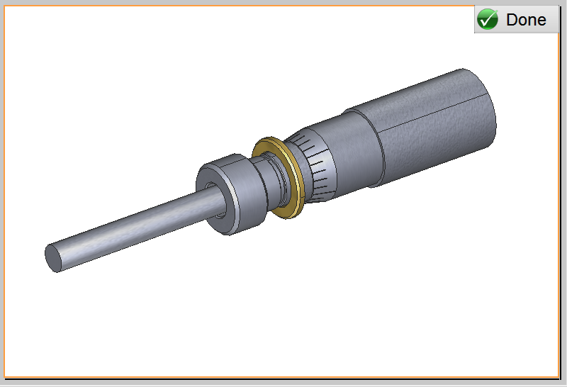
Add Front Plane Markups
Publisher3D includes a variety of markups. We will start with simple 2D text and image overlays, and then add a 3D markup. The illustration saves the markup information, so changing illustration will change markups or remove them if the illustration does not include any markups.
First let’s add a simple title as an overlay for this illustration.
Enter Markup Mode
- Click the “Illustrate Ribbon”
- Verify that you are in edit-markups mode. If you are, then the view will be enclosed in an orange box, and the “Edit” button will be shown as pressed in the Illustrations ribbon group.
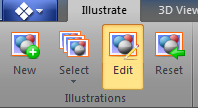
Illustrations Ribbon Group (Edit)
If you are not in edit-markup mode, simply click the “Edit” button in the Illustrations group.
Add a Text Markup
- Click on “Text” in the Illustration Tools group.
- Observe that the 3D view now displays a grid overlay which indicates the drawing plane for the markup. Also, notice that when you mouse over the 3D view, the mouse cursor indicates that you are ready to draw a markup onto the grid.
- Left-click in the top left, hold down the mouse, drag out a box about the size of one of the major grid divisions, then release the mouse button.
- Notice that when the mouse is released, a dialog box is displayed for entering text.
- Enter “Spindle Subassembly” the text box and click OK.
- The text is now displayed using the currently selected font. Notice that the text is selected as indicated by the handles.
- Change the font size to 18 by using the pulldown in the Font group on the Illustrate Ribbon.
- Now, use the color pulldown in the Font group to change the text color to the top blue color.
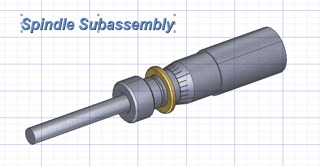
Markup Text
Publisher3D includes a set of images that are useful for technical documentation. Let’s add a generic “inspection” icon.
Add an Image Markup
- Verify that you are still in edit-illustration mode by verifying that the “Edit” button on the Illustrate Ribbon is depressed and there is an orange border around the 3D view.
- Click on the pulldown arrow beneath the Image button in the Illustration Tools ribbon group. Scroll down and click on the magnifying glass icon.
- Observe that the mouse cursor indicates that you are ready to drag out the image.
- Left click, hold down the mouse, drag a small square about the size of a major grid division in the bottom-right corner below the 3D model, the release the mouse.
- If your image has an outline, you can turn this off from the “Line” pulldown in the Color ribbon group. Pick “No Line” at the bottom.
- Click “Done”.
- Observe that the grid is hidden and the Storyboard updates the illustration thumbnail to include the markups that you have added.
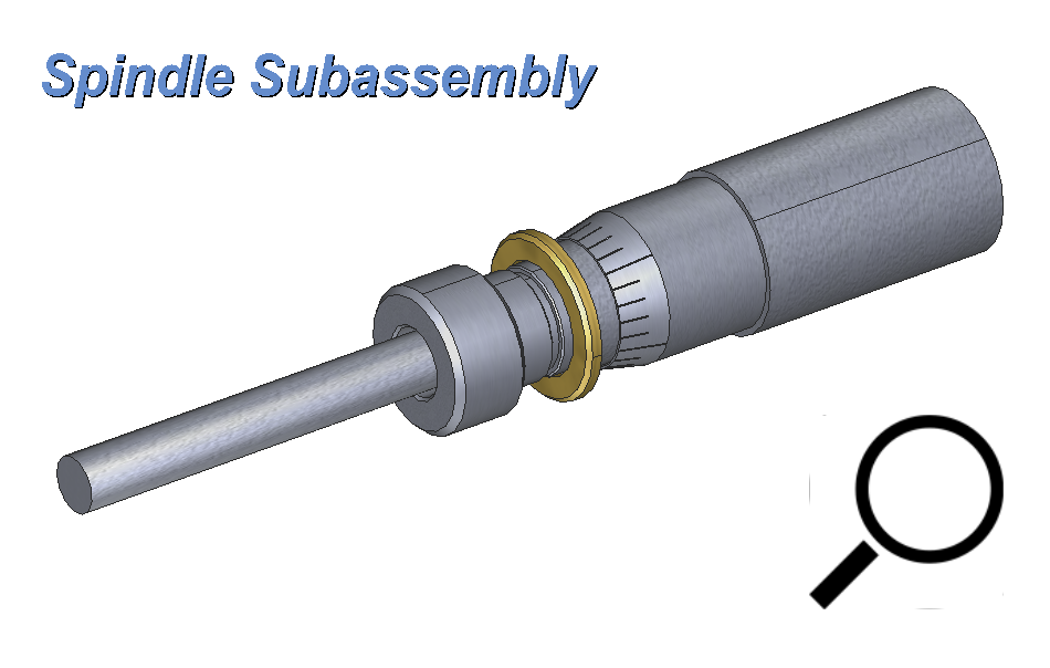
Image Markup
Add 3D Markups
Markups can be drawn onto a 3D plane as well. These are called 3D markups and are very useful for adding arrows and other indicators of action in the 3D space. Like other markups, they are associated with an illustration and will not be displayed with other illustrations.
Add a 3D Markup
- Verify that the “Markup View” illustration is selected in your storyboard. If it is selected, then it will be highlighted with an orange border. If it is not selected, then click it in the Storyboard panel to select it.
- Click on the pulldown under “Grid” in the Draw Plane ribbon group and select “3D-XY”.
- Notice that the grid plane used for drawing markups is now displayed in 3D space.
- We now need to position the grid in the Z-axis. Click “Position Grid” in the Draw Plane ribbon group.
- Notice that the mouse cursor.
- Click on the model about halfway down to set the grid intersection. This is the plane that you will draw markups onto.
- Now, click on the pulldown under “Shapes” in the Illustration Tools ribbon group and the select an Arrow shape.
- Notice that the mouse cursor indicates that it is ready to draw a shape onto the grid.
- Left click on the 3D grid, hold the mouse button down, drag out the position for your arrow and then release the mouse button.
- Notice that the markup is created and then automatically selected.
- Use the handles to scale and rotate the arrow as desired. Hold down CTRL while rotating to lock rotations to increments of 45 degrees.
- Click “Done” to accept the changes.
- Use the mouse to rotate the 3D view and observe the behavior of the 3D markup.
Reset the View, Again
Now that we have added this illustration and are ready to move on to our next illustration, let’s reset the view again.
Reset the View
- Press the ESCAPE key to clear the illustration. This will clear the markups.
- Right click the 3D view and select “Show All” from the 3D menu. This will bring back the parts the we hid to create the previous illustration.
- In the Viewpoint ribbon group, click on the Home button.
Updated less than a minute ago
